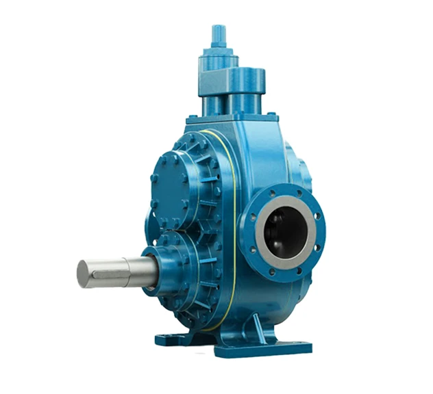
Our Helical External Gear Pump is designed for high flow, large transfer applications and versatility within industrial settings. The external gears feature lower operating speeds and helical (angled) teeth in place of straight teeth, for a gradual operation. Additionally, these pumps are ATEX-approved for use in hazardous environments.
Typical applications include:
| Specification | YHL 2 | YHL 2½ | YHL3 | YHL 4 | YHL 8 | YHL 10 |
|---|---|---|---|---|---|---|
| Max Capacity (m³/hr) | 12 | 38 | 38 | 76 | 250 | 250 |
| Max Pressure (Bar) | 10 | 15 | 15 | 15 | 15 | 15 |
| Max Viscosity (cPs) | 55,000 | 55,000 | 55,000 | 55,000 | 55,000 | 55,000 |
| Max Speed (rpm) | 1500 rpm | 900 | 450 | 450 | 450 | 450 |
| Max Temperature (°C) | 200 | 350 | 350 | 200 | 200 | 200 |
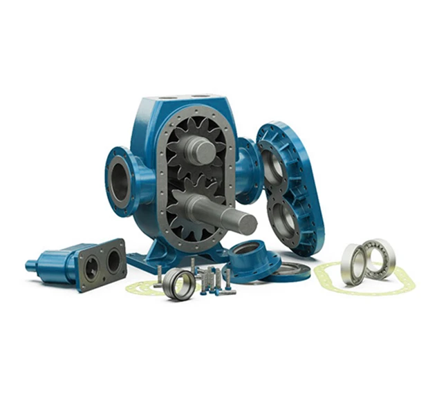
How does a Helical Gear Pump work?
A horizontal-shaft pump with two external helical gears. As the shaft turns, the gears draw liquid into the inlet, trap it between the gear teeth, and carry it around the casing to the outlet.
By-Pass/Pressure Relief Valve Operation:
A By-Pass or Pressure Relief Valve (PRV) protects the pump and drive unit from damage caused by over-pressurisation, typically resulting from closed-valve operation or blockages in the discharge line. It can be installed on the pipework as a By-Pass Circuit, routing fluid back to the pump suction or tank, or fitted directly onto the pump head.
When opened, the By-Pass relieves excess fluid and pressure from the discharge side back to the suction side, allowing the pump to recirculate within itself until the blockage is cleared or the closed valve is reopened and line pressure returns to a safe level.
Being spring-loaded and adjustable, By-Passes can be tweaked in situ to suit changing system or pump requirements.