Products
Comprehensive Product Portfolio:
Explore our extensive range of over 18+ pump types, tailored systems, bespoke solutions, & comprehensive spares.
View Full Range
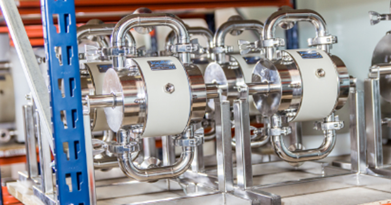
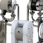
Air-Operated Diaphragm Pumps:
Our Diaphragm Pumps use no-nut, clean-face diaphragms, can self-prime & handle corrosive, abrasive & viscous fluids.
View Full Range
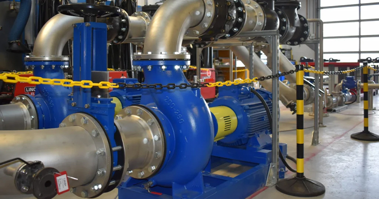
Centrifugal:
Our Centrifugal Pumps come with open, semi-open & closed impellers. Self-priming, ATEX-rated & multiple configurations.
View Full Range

Peristaltic:
Our Low & High-Pressure Peristaltic Pumps can self-prime up to 9m, with hoses lasting 30% longer than standard hoses.
View Full Range
Progressive Cavity:
Our Progressive Cavity Pumps are self-priming and well-suited to highly viscous, shear-sensitive & heterogeneous fluids.
View Full Range

Flexible Impeller:
Our Flexible Impeller Pumps with rubber impellers & housed vanes handle thin, viscous & shear-sensitive fluids.
View Full Range
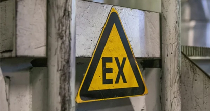
ATEX:
Our ATEX-certified Pumps are built from conductive materials to ensure safety & compliance in hazardous environments.
View Full Range
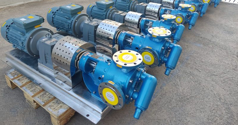
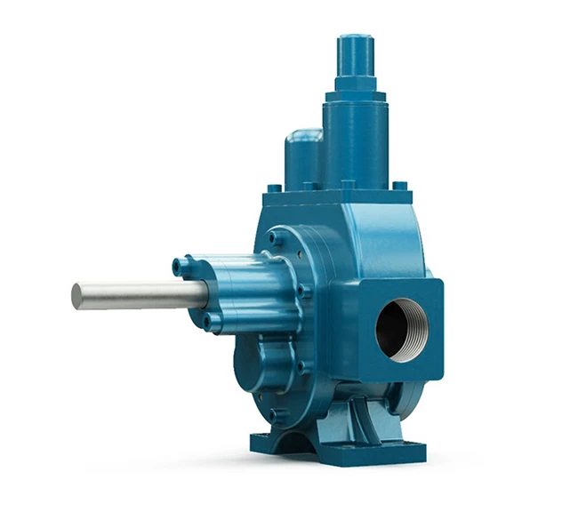
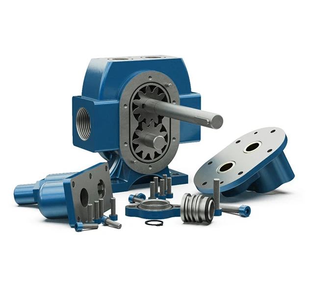
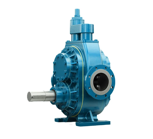
Gear:
Our internal & external Gear Pumps handle high-viscosity fluids, offer bi-directional flow & suction lift capabilities.
View Full Range
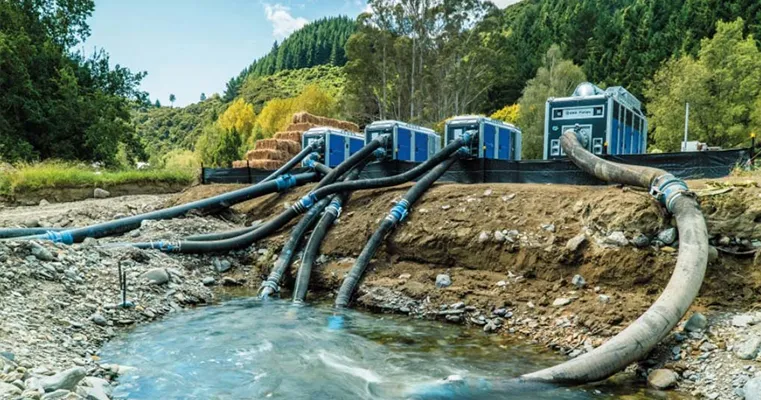
Diesel-Driven
Robust diesel-driven pump sets for mobile, high-demand Industrial applications like Wastewater Management, Irrigation, and Agriculture.
View Full Range
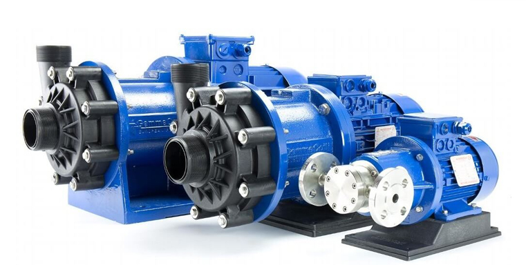
Mag Drive:
Our Magnetic Drive Pumps are available as Vane, Centrifugal, or Turbine Mag Drive Pumps for Industrial & Hygienic uses.
View Full Range
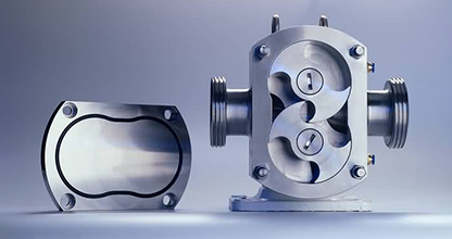
Lobe:
Our Lobe Pumps handle slurries, pastes & solids-laden fluids, supporting CIP & SIP, with EHEDG & FDA-approved variants.
View Full Range
Twin Screw:
Our Twin Screw Pumps feature wear-resistant mechanical seals & a double-chamber design, supporting CIP/SIP tasks.
View Full Range

Submersible
Our Submersible Pumps are suited to drainage & dewatering tasks, handling sludges & slurries containing particles.
View Full Range

Booster Sets:
Our Booster Sets ensure consistent water pressure with various mounting options, tailored to your application’s needs.
View Full Range

Drum Unloading:
Our Drum Unloading Systems, designed for high-viscosity Industrial & Hygienic media, achieve up to 99% product removal.
View Full Range

SLES:
Our SLES Mixing & Dilution Unit uses Progressive Cavity & Centrifugal Pumps to dilute 70% SLES to 27%, reducing costs.
View Full Range

Mixers:
Our Industrial Mixers, electrically or air-driven, remix settled product in IBCs or drums, simplifying storage & transport.
View Full Range
Mobile Solutions:
Our Mobile Solutions include decanting units & trolleys for secure liquid unloading for Industrial & Hygienic tasks.
View Full Range

Sanitary Valves:
Our Sanitary Valves, 3A/EHEDG certified & with USP VI elastomers, ensure media purity & compliance in varied industries.
View Full Range

Pump Accessories:
Our Pump Accessories such as Dampeners, Valves, Flow Meters & Frequency Inverters enhance Industrial & Hygienic pumps.
View Full Range
Industries/applications
Industries Powered by Tapflo Solutions:
Serving a broad range of industries spanning Industrial & Hygienic applications with customised process solutions.
View Full Range

Pumps for the Chemical Industry:
Our Chemical Pumps cover various temperatures, pressures & capacities, often used for the likes of bleach, SLES, & oils.
View Full Range

Sanitary Pumps for Cosmetics Transfer:
Our Sanitary Cosmetics Pumps are compliant with FDA & EHEDG standards, ensuring uncontaminated transfer of products.
View Full Range

Hygienic Pumps for Food & Beverage:
Our Food & Beverage Pumps minimise bacterial growth risks & are used to transfer products intended for human consumption.
View Full Range

Hygienic Pumps for Food & Beverage:
Our Food & Beverage Pumps minimise bacterial growth risks & are used to transfer products intended for human consumption.
View Full Range

Industrial Pumps:
Our Industrial Pumps offer superior chemical resistance & mechanical strength, with some pumps capable of handling flows up to 8,000m³/hr.
View Full Range

Pumps for the Oil & Gas Industry:
Our Oil & Gas Pumps safely & efficiently handle oil, gas & by-products under extreme temperatures & pressures.
View Full Range

Pharmaceutical-Grade Pumps:
Our EHEDG, USP VI & FDA-approved Pharmaceutical Pumps feature smooth internal surfaces & clinically tested materials.
View Full Range

Pumps for Pulp & Paper:
Our Pulp & Paper Pumps ensure smooth metering & mixing, with customisation options available for demanding environments.
View Full Range

Pumps for Shear Sensitive Fluids:
Our Shear-Sensitive Pumps are used to maintain the viscosity of the pumped media, vital for handling non-Newtonian fluids.
View Full Range
Mixing Unit - Dilute SLES 70% to 27%:
Our SLES Mixing & Dilution Unit mixes & blends SLES, a surfactant requiring dilution from 70% concentration to ± 27%.
View Full Range

Pumps for Surface Treatment:
Our Surface Treatment Pumps cover applications like galvanisation, plating, degreasing, pickling, coating & etching.
View Full Range

Heavy-Duty Pumps for Wastewater Treatment:
Our Wastewater Pumps come in close-coupled, corrosion-resistant, explosion-proof, self-priming & portable configurations.
View Full Range
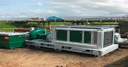
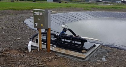
Diesel-Driven Pumps for Dewatering
Dewatering involves removing groundwater or surface water to ensure dry, stable conditions in construction, mining, and tunnelling projects.
View Full Range
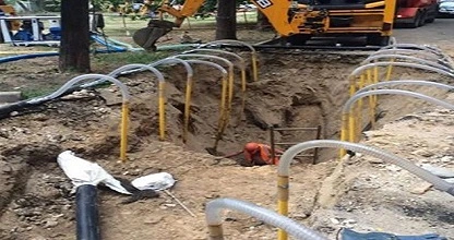
Positive Displacement Pumps for Wellpointing
Wellpoint Dewatering lowers groundwater levels by using wells & pumps with high suction abilities, preventing soil saturation & creating dry, stable conditions for Construction.
View Full Range
Engineered Solutions
Our Engineering Expertise and commitment to quality ensure we deliver high-quality, tailored pump systems for diverse industries and applications. Our expertise spans simple units to complex, advanced-featured systems, providing functionality and industry compliance.
With in-house design and comprehensive services available to support your system, Tapflo delivers bespoke solutions that meet your exact operational needs and specifications.
Design Your Own System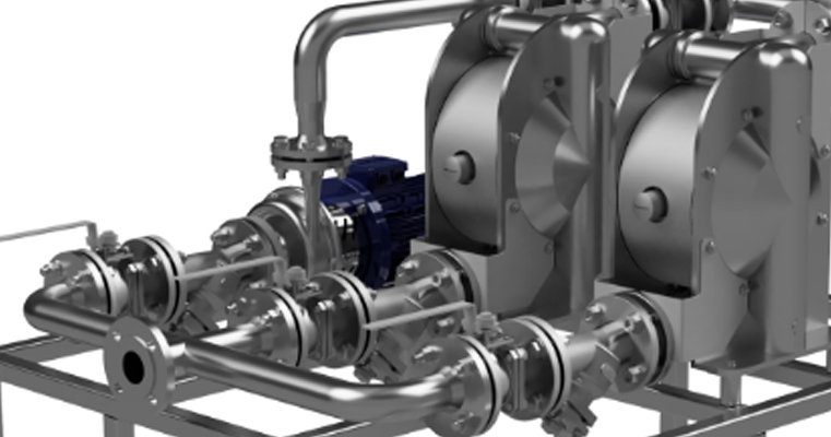
Our Brand Partners
Premier Partners of Tapflo UK:
Tapflo UK prides itself on partnering with brands that share our commitment to product quality and customer service.
View Full Range
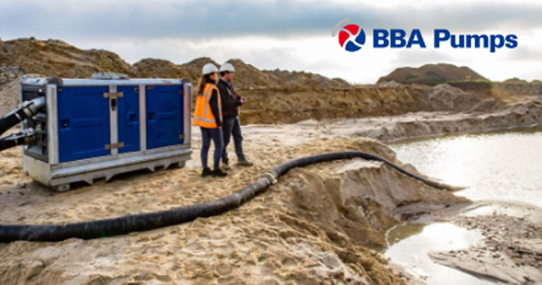
Diesel-Driven & Centrifugal Solutions:
Explore BBA Pumps’ Diesel Sets & Self-Priming Centrifugal Pumps for superior Wellpointing, Dewatering, Sewage & Flood Control Solutions.
View Full Range

Enhanced Chemical Pumping Solutions:
Explore GemmeCotti’s Chemical Pumps for acids & hazardous liquids, with Magnetic Drive, Mechanical Seal, and Vertical options.
View Full Range

Rotary Vane & Eccentric Disc Pump Specialists
Discover Jump Pumps' advanced solutions for corrosive, shear-sensitive, and high-temperature fluids. Ideal for the Food, Chemical, and Mining sectors.
View Full Range

Flexible Impeller & Liquid Ring Pump Manufacturer:
Explore Liverani’s 70+ years of expertise in high-performance pumps. Explore reliable solutions tailored for diverse industries.
View Full Range

Market Leading Progressive Cavity Pumps
Discover Nova Rotors’ ISO-certified Progressive Cavity and Wobble Pumps for Sanitary, Oil & Gas, and Chemical Processes.
View Full Range
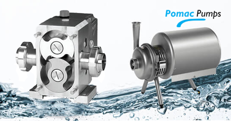
Hygienic Pumping Solutions:
Explore Pomac's leading Hygienic Pumps for Food, Pharmaceutical, Beverage, & more with a range of Centrifugal & Liquid Ring Pumps.
View Full Range

Industrial Centrifugal Pumps:
Discover Salvatore Robuschi’s ISO-compliant customisable Centrifugal Pumps, tailored for Wastewater, Oil & Gas, Chemical, & Food sectors.
View Full Range