A leading French company in the Energy-from-Waste industry approached Tapflo UK to assist with designing, building, & commissioning an EfW site for an end-user.
Application Overview
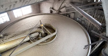
The site produces Municipal Solid Waste (MSW) Incineration Bottom Ash (IBA). This IBA is stored in a bunker prior to being loaded into lorries and disposed of offsite. The IBA is a non-combustible residue of the MSW and contains approximately 20-25% moisture when they enter the storage. This moisture leaches from the piles and accumulates at the bottom of the bunker. The client was looking for a pump assembly which allows collection of this IBA slurry/sludge and pumps it out towards waste gullies where it can then be suitably treated.
There was no access to the bottom of the bunker, so the sludge/slurry had to be pumped from the ground floor, located 7 meters above.
- Fluid: IBA Liquid Sludge/Slurry
- Temperature: 0°C to +50°C
- pH: 8 to 14
- Suspended solid content: Very Abrasive & High concentration, (stones, metal shrapnel etc)
- Flowrate: 12m³/hr
- Dry Suction Lift: <7 meters
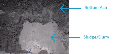
Site Requirements
| Site Requirements | Precisions | Reason |
| Compressed Air | 180.1 l/min of 4Bar air, in accordance with norm ISO8573-1 class 4. | For the Vacuum Pump |
| Power Supplies | 415 VAC / 3PH + N + E / 50 Hz (32A) | To Power Panel |
| Earthing Point | Earthing stip (10mm2) to site earth point | Earth Panel |
Equipment & System Provided
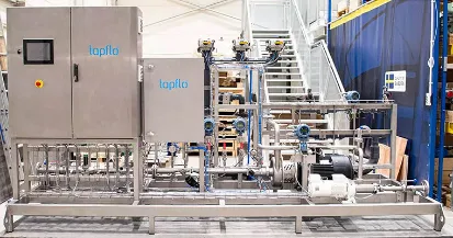
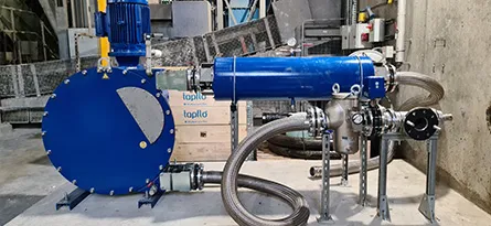
The system was designed, supplied, installed, & commissioned by the Tapflo UK Engineering Team throughout. It was designed as a turn-key solution with local controls next to the pump itself, and all necessary ancillary equipment to remove the IBA Leachate safely and efficiently from the bunker, no matter the conditions!
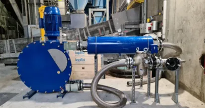
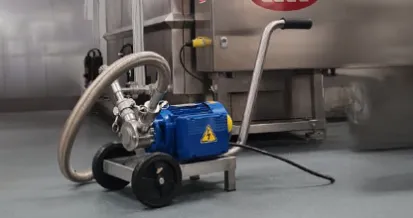
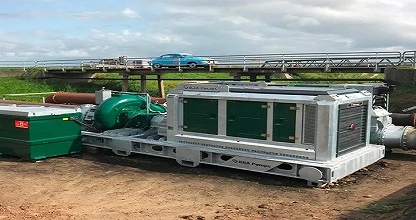
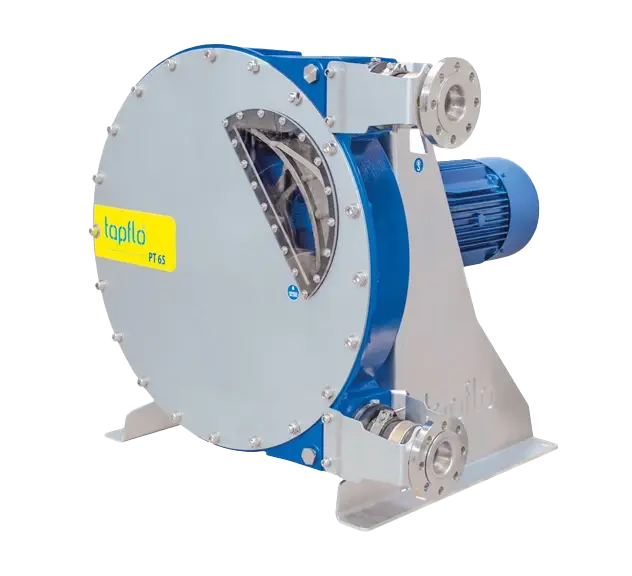
PTX80 – 3” Peristaltic Pump w/ 90° Geared reducer
A Peristaltic Pump was the best choice of technology for this project due to the unrivalled benefits of indefinitely dry running capabilities, easy maintenance, best dry suction capability (0.98Bar[g]), large solid capability (Pass solids up to <25% of hose ID) and minimal fluid contact parts.
The PTX80 size was chosen to maximise large solids handling and suction capabilities whilst minimizing footprint impact.
Other benefits of Tapflo Peristaltic Pumps are:
- Our hoses are Braided Polyamide reinforced & multi-layered, high-grade material, giving optimal chemical and mechanical resistance.
- Our pumps have a ‘longer sweep’ stroking pattern over similar performance pumps, giving our pumps a higher hose life expectancy.
- A Better Shimming strategy decreases compression on the hose, resulting in a longer lifetime.
Capacitive Sensor
The hose rupture detection sensor sends a signal to the local control panel in the unfortunate event of a hose burst. This stops the pump automatically and sounds a local alarm (audible & visual) so operators can carry out maintenance.
Vacuum Assist Pump System
The Vacuum Pump aids in high viscosity / high suction lift applications by creating a vacuum inside the pump casing, preventing the pump hose from collapsing on itself. The vacuum pulls the hose apart so that the cavity inside the hose can be filled with air, discharging it from the suction line.
Ultrasonic Flow Switch
An Ultrasonic Flow Switch was put on the suction line, to detect when flow has reached a set point. Once this activates, it sends a signal to the local control panel, shutting a solenoid valve on the pneumatic line to the vacuum pump, preventing wasted air.
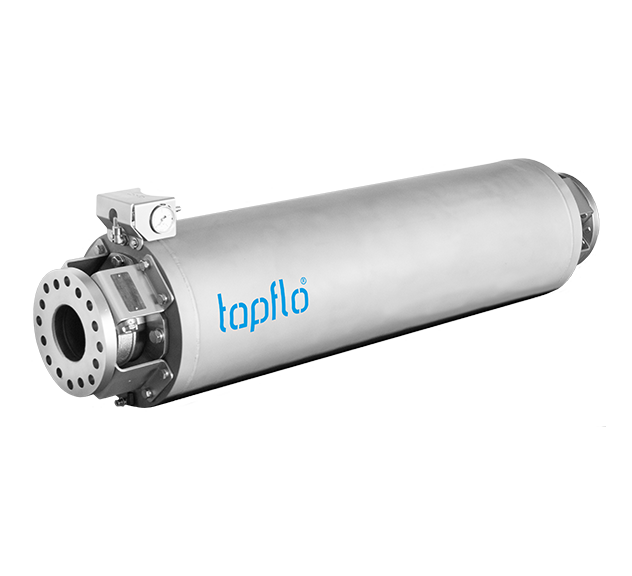
Pulsation Dampener
The pump discharge was fitted with a suitable In-line pre-charged Pulsation Dampener. Due to the pump size, there is pulsation in the discharge line. Whilst there is no flow reading instrumentation on this system because it uses flexible hosing, the Tapflo engineers opted to install this for health and safety reasons, to prevent pulsation kicking the discharge hose around, and potentially hitting operators.
The PTP series in-line pre-charged pulsation dampeners are designed for the PT & PLT Tapflo Hose Pumps, and they utilise the same hose composition as the PT range (Polyamide Reinforced & Multi-layered). The PTP dampeners are pre-charged with compressed air and are set to two-thirds of the system pressure to achieve up to 90% pulsation reduction.
Flexible Hosing
Because of the industrial application, the system was equipped with a flexible discharge hose on the suction line and discharge line. The suction hose connected a strainer to the pump, whilst the discharge hose went from the end of the pulsation dampener to a fluid storage vessel.
The hoses were helically convoluted PTFE, ensuring optimal chemical resistance to the fluid, with an external vacuum wire due to the high suction conditions, and stainless steel over braid on top for mechanical resistance to cuts/scraping on floor/external impacts etc.
Actuated Butterfly Valve
As the system was provided as a turn-key solution, one of the cleaning protocols advised by Tapflo was to insert a manual pressure washer down the suction line of the pump once every quarter to prevent any large sediment build-ups, which would ultimately lead to a blockage. To prevent the manual pressure washer from damaging the basket inside the strainer, a suitable butterfly valve was installed just before the strainer. This is controlled via the local control cabinet so that it closes prior to carrying out the manual pressure washing protocol.
Single Basket Strainer w/ Differential Pressure Indicator
Because the bunker is located near the waste metals bunker, it is possible that solids too big to process find their way into the IBA bunker. Whilst the automated ash-collection claws above the bunker are set to detect and automatically remove any large solid waste from accumulating inside the IBA Bunker, it is still possible that large stones or metal particulates remain inside the bunker.
Due to this, a Basket Strainer fitted with ø15mm perforated mesh was installed on the suction line which collects and contains any solids too big for the pump to process from getting to it. The differential pressure indicator monitors the pressure inside the strainer itself, and once filled, it sends a signal to the local control cabinet, automatically stopping operation and sounding an alarm (audible & visual), so an operator can clean the basket strainer out.
Local Control Cabinet
The Control Panel was designed, built, wired, & programmed by our in-house engineers. It was made as a turn-key solution, incorporating all the safety measures needed to conform to today’s health and safety standards, and was programmed to control the system entirely, without external intervention being required other than connecting pipework up.
The system was set with various protocols, covering normal operation, reversing features, stirring functionality, maintenance activities, internal cleaning modes and more.
The panel itself is a powder-coated steel enclosure, incorporating a 7” coloured touchscreen HMI, 15kW Inverter, PLC, alarm system and more.
Suction Pipework inside the bunker
Because the ash collection claws constantly operate inside the bunker, robust heavy-duty (SCH160) pipework was used, and specialist protective barriers were welded to bolt over the top of the pipework to prevent/mitigate impacts from the ash claws.
Installation & Commissioning
The system was fully installed by Tapflo Engineers during the plant’s planned outage in 2021. The pump was installed on a concrete plinth, and the system was fitted onto stainless steel unistrut supports where appropriate. The panel was mounted to the bunker wall, with the external cabling being neatly organised in stainless steel cable trays and steel cable tied down for neat cable management.
Phase 1 Installation:
- Pulsation Dampener fitted to pump discharge during installation
- Vacuum Assist System fitted to Peristaltic Pump
- Mains breaker and isolation feed to control panel
- Control panel installation
- Phase one installation before panel and further supports
Phase 2 & 3 – installation and commissioning:
The system was then successfully commissioned by Tapflo engineers, who ran through all features of the system on-site ensuring correct operation. Safety concerns were checked, including checking fuses / MCB / Internals, tug testing wires, correct cable management etc. The system was then tested with water first on a surface level and then moved into the bunker.
Training & Documentation
Five total training days were provided by Tapflo UK to ensure all operators, maintenance staff, and electrical staff can correctly use, maintain, and interact with the system.
Due to the type of industry the end client serves, much documentation was provided by Tapflo UK. This includes, but is not limited to:
- Bespoke (System & Client Specific) IOM Manual for complete system
- Performance Testing
- Suction capability Testing
- Hydrostatic Testing
- Electrical Load Testing
- Preventative Maintenance Planning
- I/O Lists
- Functional Analysis
- Quality Documents (including welding certificates & procedure for pipework, complete system CE / UKCA certification, system acceptance etc)
- Manufacturing Programs
- Suppliers Equipment Declarations
- Training Support Documentation

